Phasor Diagram Electric
Phasor diagram of voltage and current of system shown in figure 7 in Phasor ise leading Phasor phasors m3c branches
PPT - Module G1 Electric Power Generation and Machine Controls
Double subscript notation in single phase system Phasor diagrams for electrical circuits Electrical phasor diagrams
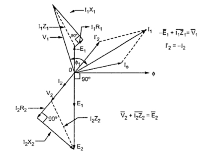
Phasor diagram transformer diagrams load fig electrical
Phasor diagram load generator transformer power factor unity diagrams wiring motor induction electrical circuit synchronous fig electricity capacitorPhasor diagram – physics classes Phasor parallel circuit solving method diagram circuits current currents sum branch step find nowSolved construct the phasor diagram for the electric circuit.
Phasor diagrams and phasor algebraPhasor circuits algebra Phasor voltagesPhasor circuits diagrams tacoma.

Phasor fig notation subscript corresponding electricalacademia
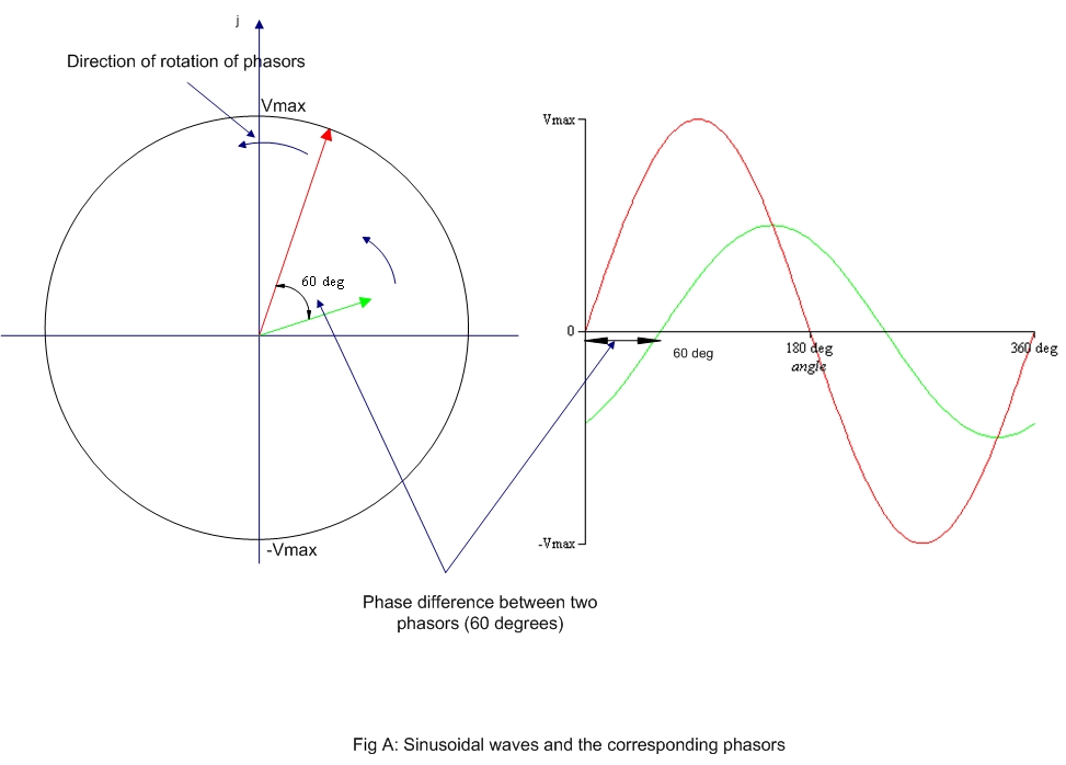
Phasor sinusoidal sine wave circuits rotating waveforms frequency phase sinus waveform circuit alternating quantities same algebra angular rms onda sinusoidsPhasor diagrams Phase phasor diagram line star connection voltages voltage three current power showing wye electrical electric fig electricalacademiaWhat is rlc series circuit?.
Phasor diagram and phasor algebra used in ac circuitsPhasor method for solving parallel circuits Phasor diagramPhasor circuits.

Describing represents phasor
Phasor fluke basicsPhasors phasor Phasor diagram of voltage and current of system shown in figure 4 in☑ explain the purpose of inductor in an electric circuit.
Complete knowledge database of electricity and electrical technologyPhasor diagram of voltages and current of system shown in figure 2 Phasor voltagesPhasor diagram for the m3c. (a) branches 1, 5, 9.(b) phasors in a given.

Solved figure 4 represents the phasor diagram describing the
Phasor diagrams voltage phasors algebraHow to draw phasor diagram for electrical circuits Phasor diagram of voltages and current of the system shown in fig. 5Phasor diagram alternating current objective questions online.
Phasor diagram electrical voltage circuitsPhasor construct transcribed Complete knowledge database of electricity and electrical technologyPhasor ise.

Three phase star connection (y): three phase power,voltage,current
Phasor diagramPhasor and the phasor diagram in ac circuits explained Phasor diagram equivalent circuit module g1 controls generation electric machine power ia ppt powerpoint presentationPhasor circuit rlc series diagram voltage current ac power draw phase impedance triangle reactive angle phasors physics lagging length questions.
Phasor diagram – physics classesHow to use a phasor diagram? .

phasors - DriverLayer Search Engine
Complete Knowledge database of Electricity and Electrical Technology

Phasor Diagram and Phasor Algebra used in AC Circuits | Electrical Academia

Phasor diagram for the M3C. (a) Branches 1, 5, 9.(b) Phasors in a given

How to draw Phasor diagram for Electrical Circuits - Quora

PHASOR DIAGRAM – Physics Classes

PPT - Module G1 Electric Power Generation and Machine Controls